XENA Project
Phase III
History
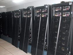
Frames being assembled
|
In September of 2002, we were contacted by Bill Reidy of the High Performance
Computing Modernization Program (HPCMP) of the Department of Defense. They
had a newer SP machine available for a site with the skills to run it.
Its form factor fits Xena I but increases the power a lot and adds a fast
global disk array. The machine was operated at the US Army Engineer Research
Development Center (ERDC) Major Shared Resource Center (MSRC) in Vicksburg
Missisippi.
The system has 126 nodes with each a 160 MHz POWER2 Super
Chip CPU, 512 MB RAM, 9 GB disk, and a 150 MB/s SP Switch. The system has
1.1 TB of global SSA disk storage in 3 racks with 16 drawers, each with
16 4.5 GB disks accessible through 16 SSA 80 MB/s adapters.
|
|
On Nov 12 Xena I was turned off and on Nov 27 it was moved
out of NPB 2250 to make room for Xena III.
On December 8, Ryan Chancey, a QTP student, and Erik Deumens
drove the 750 Miles trek to Vickburg in a rental car to prepare the system
for loading. A Mayflower truck with 53 foot trailer was scheduled to be
at the ERDC site on Tuesday December 10. With the help of Charles Ray and
Tim Dunaway, all the components were prepared for shipping on Monday.
With the help of Charles, Tim and Owen of ERDC and the truck
driver Roy Rowls the 12 frames each weighing from 800 to 1800 lbs. was loaded
by noon.
Ryan and Erik drove back with a stop-over in New Orleans
and the truck was unloaded at UF Thursday morning, December 11.
|
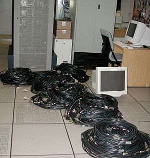
6400 feet of switch cables and the
control workstation
|
Architecture
Node and switch frames: the switch frame 9 in the middle
|
Xena III has 118 nodes with a 160 MHz POWER2 Super Chip processor and 512
MB RAM and 9 GB of local SCSI disks. The Xena III system incorporates the
10 Winterhawk I nodes of Quanta. These nodes have two 200 MHz POWER3 CPUs
and 1 to 4 GB of RAM and 2 18 GB disks. By incorporating these nodes into
Xena III, they will gain access to the fast disk array, allowing them to
be much more useful. The total node count is thus 128 and the total CPU
count is 138.
Each node is connected to all other nodes with a fast SP
Switch capable of 150 MB/sec full duplex transmission.
The entire system is connected to the QTP private backbone
network switches via 8 10BT and 10 100BT Ethernet connections.
Eight nodes are connceted to an array of 256 external SSA
4.5 GB disks for a total of 1.152 TB of global storage.
|
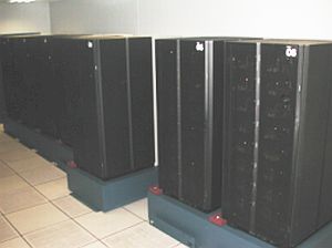
Assembling
the system
During the month of August 2003, the racks of the system were put into
place and all cables were laid under the floor.
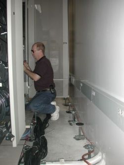
Erik working on Xena III
|
A computer like Xena III has many components that need to be put in
place and connected.
The pieces are:
-
A control workstation, which connects by serial cables to all node
frames and the switch frame and by Ethernet to all all nodes
-
Eight nodes frames with each 16 nodes and 1 150 MB/sec switch
all need a 30 A power cable, a
serial cable for hardware control (power on and power off and
diagnostics), 16 fat switch cables, an Ethernet cable, and four frames
with Input/Output nodes also have 16 SSA cables going to the disk racks.
-
A switch frame with 4 150 MB/sec switches has a power connection, a
serial connection for hardware control and 128 fat switch cables going
to the 8 switches in the 8 node frames.
-
Three disk racks with 4 or 6 disk drawers with a total of 1.1 TB of
disk space all need a 30 A power cable and 16 or 24 SSA cables to
connect to the I/O nodes.
|
All parts have to be put in places so that all necessary cables will
reach. The cables all go under the floor.
The 64 SSA cables each 90 feet long need to be inspected and bundled
in groups of 16. Graduate students Julio Palma and Luis Galiano helped
straightening out the cable mess.
|
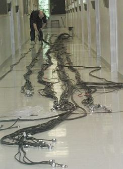
1 mile of SSA cables down the hallway
|
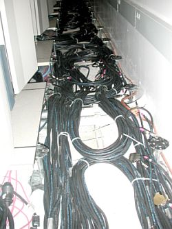
Switch cables in the space under the floor.
|
To ensure that the right cable is connected to the right adapter,
all cables must be labeled on both ends with some meaningful tag,
showing where the connection should be made in the node or in the disk
drawer.
Once they are labled they can be put under the floor. Avoiding tabgles
and knots is important, both to avoid damage to the cables and to make
sure that the cold air from the room cooling system can still reach
all parts of the room.
On Friday through Sunday of Oct 10-12, 106 nodes were installed
from the control workstation and 8 boot-install servers. There were
about 100 jobs in the queue already. As nodes became available, jobs
were being processed. By Monday morning the first bacth of jobs were
done and a second batch was submitted.
Unfortunately, 22 nodes had a hardware problem that prevented them
from powering on and during the Monday after installation 3 of the
nodes that installed and ran successfully, developed the same problem.
|
Building
a working system
During several weeks, the Remigio Trujillo and Erik analysed the
broken nodes. It definitely was a power problem and the IBM
engineering manuals lead to the power control board being
bad. Replacing that board on a bad node with one from a good node did
cure the problem. During these weeks several more nodes died.
We considered the option to buy new boards, but it was not clear what
caused such a massive failure rate in just that board.
Further inspection of the many broken nodes revealed that there must
have been significant water damage during the time the system was in
storage outside a climate controlled computer room. We knew that the
system had been stored in a building with a leaking roof. There was
probably no water in the nodes from the rain, but from condensation of
extreem humidity. In many nodes this must have started corrosion of
electrical contacts. For some nodes the problem was so bad that they
failed basic power tests by the power control board after a few hours
running. Some nodes only failed after several weeks. Some nodes
survived the corrosion.
We decided to build an 8 frame system with the good nodes. In December
the nodes that were still operating, and running jobs, were moved into
frames 1, 3, 5, 7 and 8. Frames 4 and 6 just held broken nodes and
frame 2 still had 9 working nodes. We then installed the softare again
on the nodes that were moved. Finally we had a stable system with 90
nodes: Out of the 126 nodes we had received 46 have died, leaving 80
160 MHz nodes. To that we added in frame 8 the ten 200 MHz Winterhawk
I nodes from the old QTP QUANTA system.
The 150 MB/sec switch had been running all this time between the nodes
that were operational and it was now reconfigured for the new active
nodes.
Building
the global GPFS file system
Eight nodes are attached to 256 4.5 GB SSA disks. The disks are arranged
in 3 racks with 4 to 6 drawers each. The eight nodes are divided into four
pairs and each pair is connected to a group of four drawers.
Around December 20, the SSA loops and adapters were chcked and
tested. It turned out that two SSA cables from nodes 3 and 4 in frame
5 going to the third disk rack had internally broken
connectors, and they were replaced with new cables.
On December 31 all disks were configured as RVSDs on all 89 nodes and
the recoverable virtual shared disk system was started.
These recoverable virtual shared disks (RVSD) are the layer on top of
which the general parallel files system (GPFS) is defined.
| Disks |
Rack 1 |
Rack 2 |
Rack 3 |
| Drawer 6 |
|
72 GB |
72 GB |
| Drawer 5 |
|
72 GB |
72 GB |
| Drawer 4 |
72 GB |
72 GB |
72 GB |
| Drawer 3 |
72 GB |
72 GB |
72 GB |
| Drawer 2 |
72 GB |
72 GB |
72 GB |
| Drawer 1 |
72 GB |
72 GB |
72 GB |
| Nodes |
Frame 1 |
Frame 3 |
Frame 5 |
Frame 7 |
| Node 6 |
yena02 |
yena22 |
yena42 |
yena62 |
| Node 5 |
yena03 |
yena23 |
yena43 |
yena63 |
|
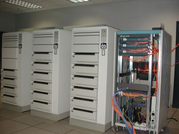
GPFS disk racks
|
|
Each node in the pair has two SSA adapters called ssa0
and ssa1 and each adapter has two ports called A and B
which can be connected to one loop each. The set of three drawers contains
48=3x16=4x12 disks and is divided into four loops. Each loop contains 12
disks and one adaper/port of each node. Every disk has a primary node, which
under normal operation does all data access to the disk, and a backup node,
which will take over the data access to the disk in case the primary fails.
This way the global data is always accessible even if one node fails.
Each SSA port has two access points to the loop A1
and A2 or B1 and B2. the SSA protocal allows
full access and data transfer along both paths at the same time for a total
of 2 reads and 2 writes at 20 MB/sec.
By choosing the disks primarily assigned to xena02
as those closest to xena02 in the loop, we make sure that no data
access from xena02 will interfere with data access from xena03
to its disks. Thus allowing maximum performance from both nodes to all
their disks. When one node is down or the loop is broken, the other node
still has access to all disks, but maybe at less performance.
Disks are grouped together into building blocks called VSD
(virtual shared disks). All VSDs are made into one global files system
using GPFS, general parallel files system, and is accessed as /scr_2 on
every node in the system.
Last modified Erik Deumens, Dec 31, 2003
|
|