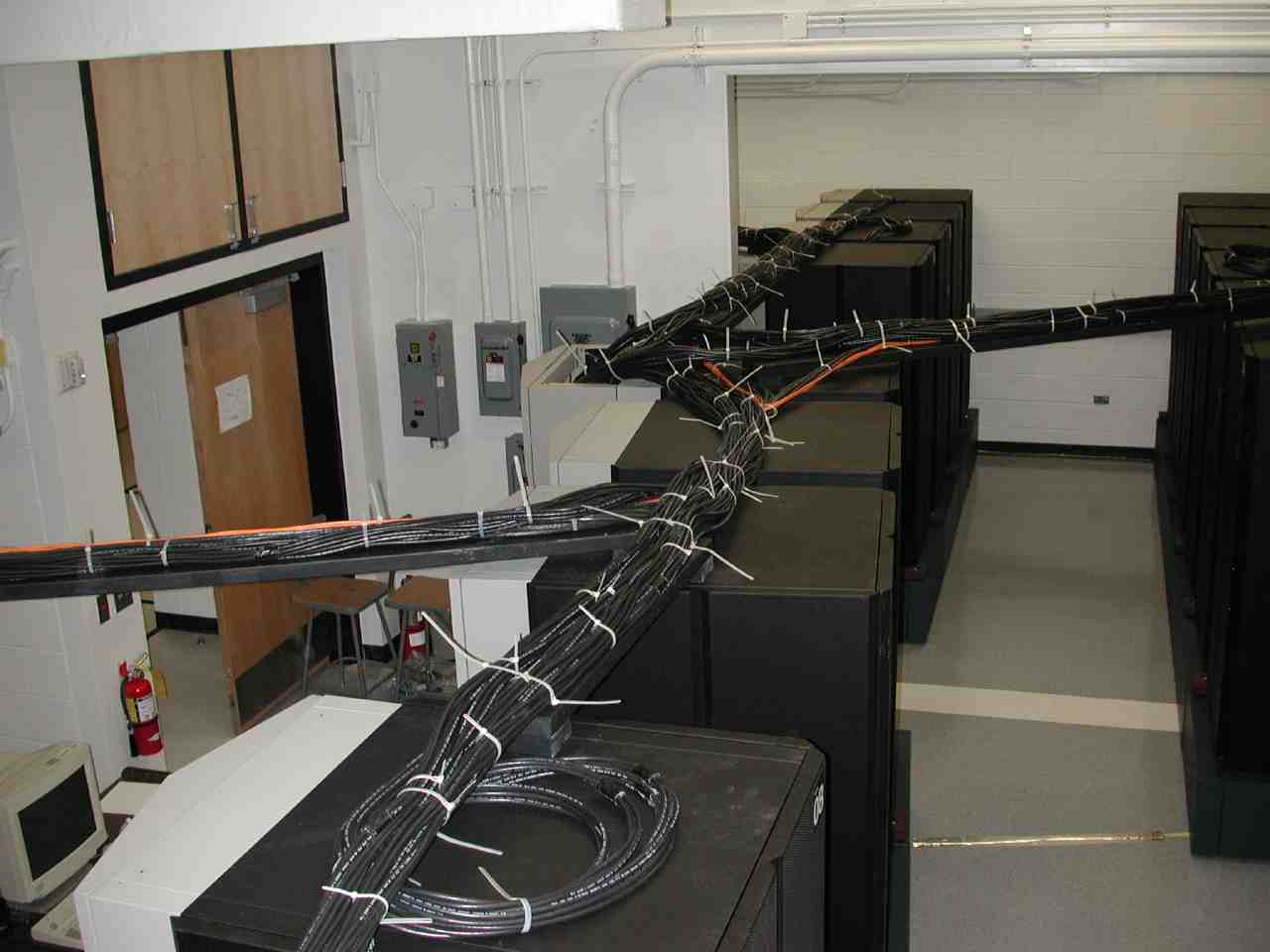
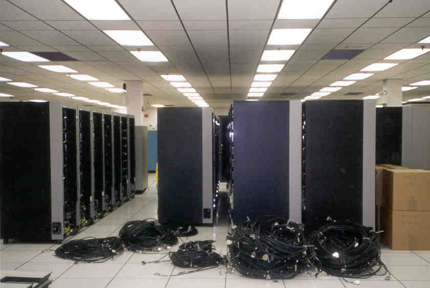
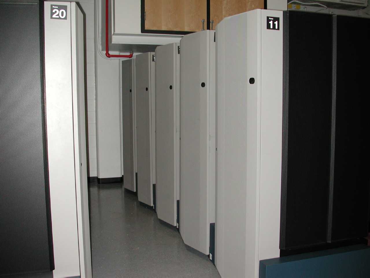
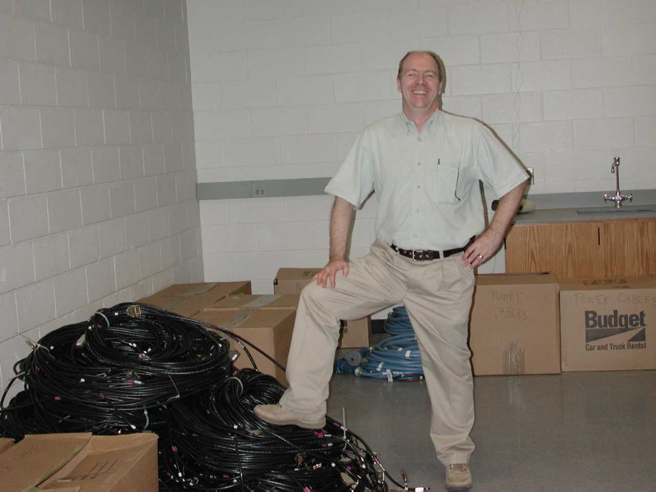
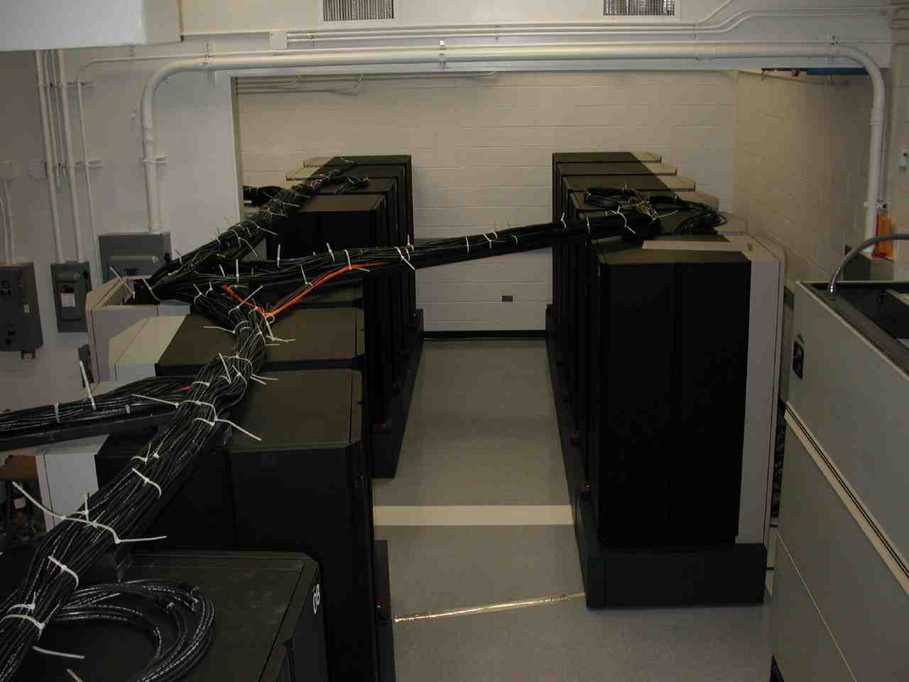
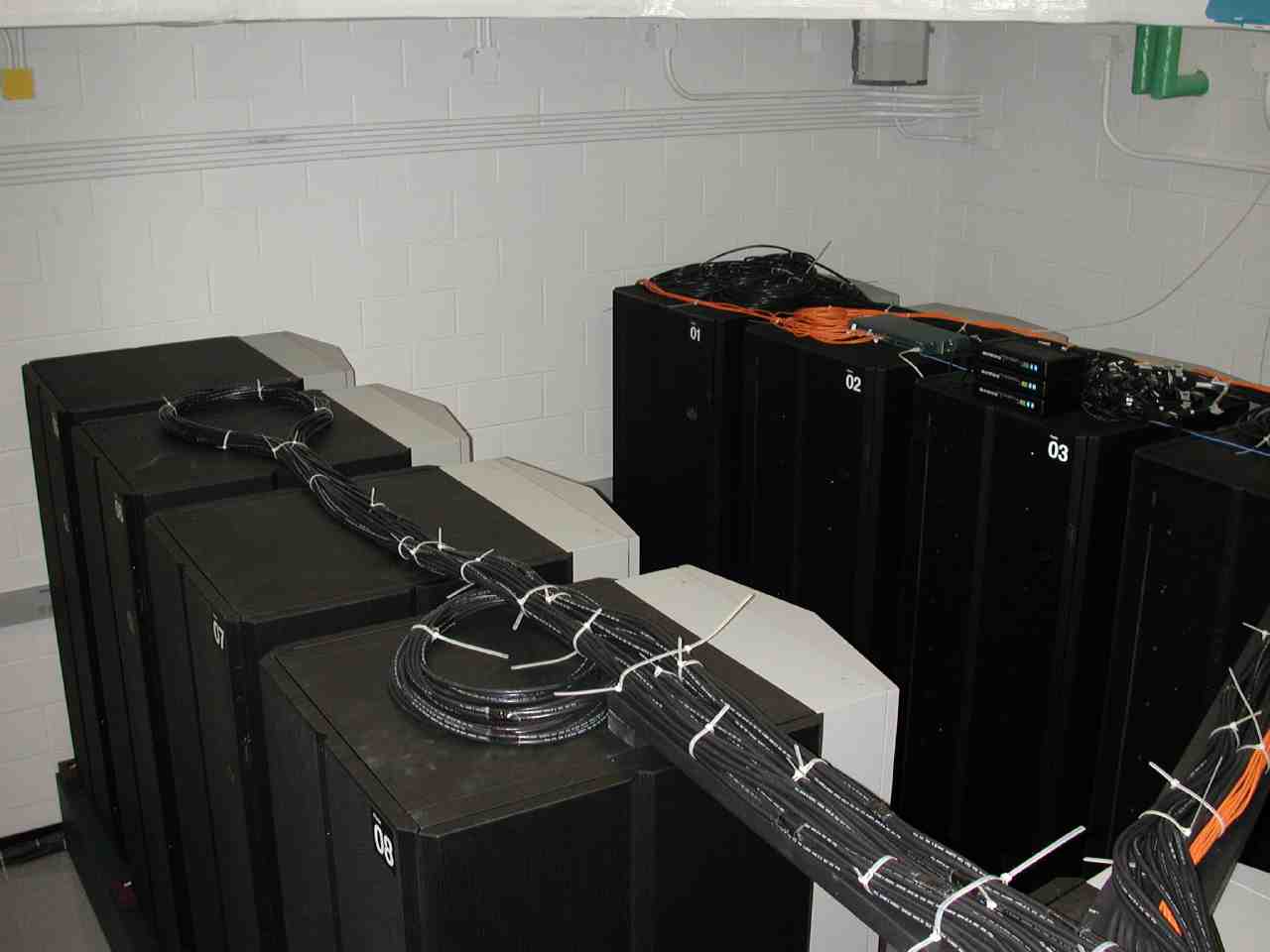
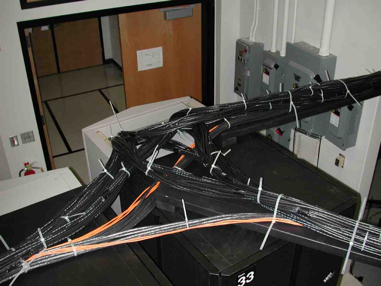
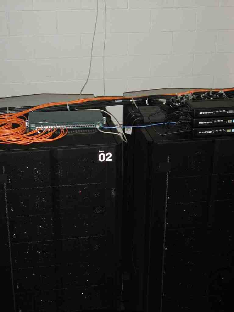
Making the correct paths for the 192 cables that connect the 6 switches
in each pair of node frames to the 8 switches in the centrally located
switch frame proved to be a challenge. The length of the cables was barely
long enough to reach because of the shape of the room and because of the
fact that we put the cables up high. The advantage of putting the cables
high is that they are visible to visitors and shows the complexity of the
system more clearly. With a raised computer room floor, that complixty
is hidden from visitors.
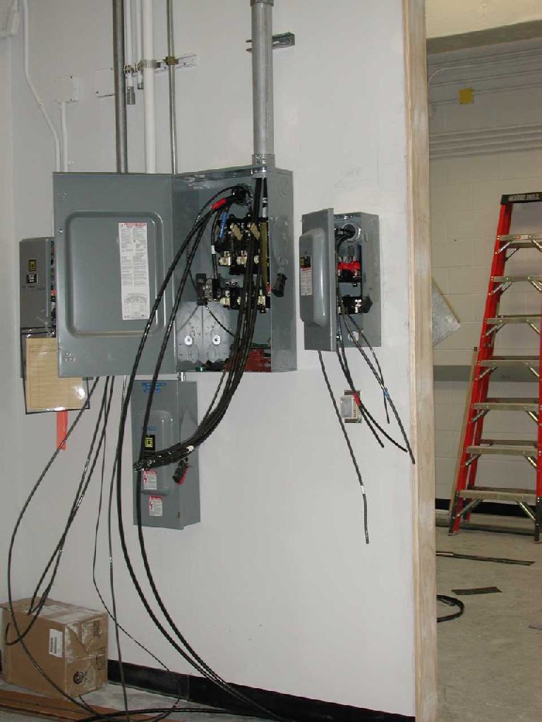
Power Up
On April 12 at 11 am the system was powered up. It is fed by 3 breakers,
1 of 200A and 2 of 100A. With the system completely switched on the 200A
breaker was measured to supply 69A on each phase (very much in balance)
and the 100A breakers were giving 36A per phase. At startup 4 nodes and
1 switch were showing diagnostic lights of trouble. Once the control workstation
installation is progressed some, it will be possible to run diagnostics
on these nodes to determine what repairs are called for.
Four power supplies were replaced, on April 26, from the spare part
pool. This did not cause any down-time since the frames each have three
power supplies, one of which is redundant.
One of the twenty SP switches had a bad supervisor card. It too was
replaced, on May 16, with a switch from the spare parts pool.
These hardware failures were discovered during the software installation
and configuration of the control workstation. During this process, one
gains increasing control and information about the system as a whole.
First job
On July 31, LoadLeveler was started on about 147 nodes and they
started taking jobs. The first project was a novel protein folding
algorithm invented by Adrian Roitberg and implemented with Robert
Abel, an undergraduate working at QTP. The work consisted on 512 jobs,
each taking about 6 days.
While Xena II was working on the 512 jobs, nodes were repaired and
taken into service. On August 23 all 192 nodes were up and running and
the SP Switch was operating between them.
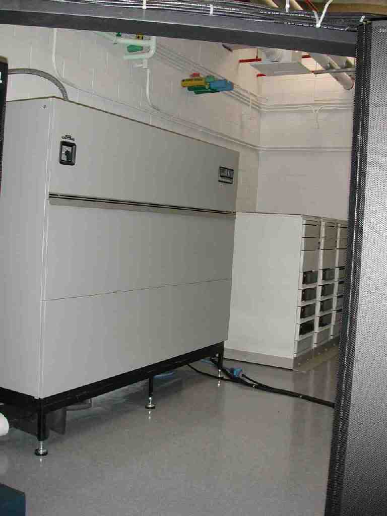
Building the global GPFS file system
Eight nodes are attached to 192 disks with 2.2 GB each using SSA
serial storage architecture, the precursor to the Fibre Channel
Arbitrated Loop architecture standard.
The disks are arranged in 3 racks with 4 drawers each. The eight nodes
are divided into four pairs and each pair is connected to a row of
three drawers, one in each rack.
| Disks | Rack 1 | Rack 2 | Rack 3 |
| Drawer 4 |
35.2 GB |
35.2 GB |
35.2 GB |
| Drawer 3 |
35.2 GB |
35.2 GB |
35.2 GB |
| Drawer 2 |
35.2 GB |
35.2 GB |
35.2 GB |
| Drawer 1 |
35.2 GB |
35.2 GB |
35.2 GB |
| Nodes |
Frame 2 |
Frame 4 |
Frame 6 |
Frame 8 |
| Node 5 |
xena0a |
xena1a |
xena2a |
xena3a |
| Node 3 |
xena09 |
xena19 |
xena29 |
xena39 |
Each node in the pair has two SSA adapters called ssa0 and
ssa1 and each adapter has two ports called A and
B which can be connected to one loop each. The set of three
drawers contains 48=3x16=4x12 disks and is divided into four
loops. Each loop contains 12 disks and one adaper/port of each
node. Every disk has a primary node, which under normal operation does
all data access to the disk, and a backup node, which will take over
the data access to the disk in case the primary fails. This way the
global data is always accessible even if one node fails.
Each SSA port has two access points to the loop A1 and
A2 or B1 and B2. the SSA protocal allows full
access and data transfer along both paths at the same time for a total
of 2 reads and 2 writes at 20 MB/sec.
By choosing the disks primarily assigned to xena3a as those
closest to xena3a in the loop, we make sure that no data access
from xena3a will interfere with data access from xena39
to its disks. Thus allowing maximum performance from both nodes to all
their disks. When one node is down or the loop is broken, the other
node still has access to all disks, but maybe at less performance.
Disks are grouped together into building blocks called VSD (virtual
shared disks).
All VSDs are made into one global files system using
GPFS, general parallel files system, and is accessed as /scr_2 on
every node in the system.
VSD with striping across adapters
Each VSD has one disk
in each loop connected to a host and data is striped across all
4. This way each write to
one VSD can proceed on each adapter freely to get high performance.
The loops and VSDs for /scr_2 look as follows
The labels next to the disks designate the global name of the disks.
We take one disk from each of the four loops a node is connected to
and put them together in a group of four and stripe them for optimal
performance. Such a group is called, e.g. d3c1h0na, which
stands for
drawer3connector1hopcount0nodea. The
connector can be 1 or 2 in each of the four loops (two adapters and
two ports). The hopcount is the number of hops from the connector to
the disk. The node designates the primary node for the disk.
VSD as string on an adapter
A second file system /scr_3 is constructed a bit differently to compare
the performance.
Here each VSD is build out of the 6 disks in each loop closest to the
adapter.
Although the layout of /scr_2 optimizes writes for a single VSD,
the GPFS files system always balances the load across all VSDs. Thus
every write to one VSD will be acompanied by writes to other
VSDs. Then the layout of /scr_2 may see contention on all loops,
whereas the layout /scr_3 will not. It is not clear a priori which
will be better. Maybe no option is better for every application.
One may be better for some read/write pattern. That is why we do the
test.
This second file system turns out to be 10% faster.
The labels next to the disks designate the global name of the disks.
Such a group is called, e.g. d0a0pan9, which
stands for
drawer0adapter0portanode9. The
adapter can be 0 or 1 and port can be a or b to make four loops (two
adapters and two ports). The node designates the primary node for the
disk.
VSD equal to one physical disk
The final form of the global scratch file system has one VSD per
physical disk. That way GPFS can optimize performance of acces to all
adapters and VSD servers. This form was implemented on Dec 18 2002
and resulted in /scr_2 size of 410 GB. This last configuration
turns out to be another 25% faster.
Configuration of Xena II
The XENA II system has 192 nodes with each a 135 MHz POWER2SC CPU,
1 GB of RAM and 9 GB of disk space. All nodes are connected by a 150
MB/sec full duplex, redundant path SP switch. The system has 420
GB of global storage consisting of 192 2.2 Gb disks on 16 SSA adapters
made available to each node through the SP switch as a GPFS (general parallel
file system).
Applications
XENA II will be used mostly for large scale production runs and for
experimentation with applications that require large RAM, MPI
programming, parallel algorithms and parallel I/O.
The standard distributed memory programming style with message passing,
most of the MPI 2.0 standard, and the IBM specific low-latency programming
style with LAPI, and the Cray T3E programming style with the SHMEM are
supported.
The system is suited for naturally parallel problems that Beowulf
clusters can run, but it also supprts problems that need fast access
to large global datasets and problems that require fast internode
communication, such as problems involving Fast Fourier Transforms.
|